First let's get R1 and R2 configured with route-maps and dual NAT. Here is how.
** Create an access list to match traffic to be natted **
R1#sh run | incl access
access-list 1 permit 10.0.0.0 0.0.0.255
** Create route-maps to NAT out of eBGP interface gig2/0 and iBGP interface fast1/1 **
R1#sh run | sec route-map
route-map iBGPNAT permit 10
match ip address 1
match interface FastEthernet1/1
route-map eBGPNAT permit 10
match ip address 1
match interface GigabitEthernet2/0
** Create NAT statements using route-maps so the traffic can get natted appropriately. The reason we are doing it this way is because if R1's connection goes down with R4, R3 can still get to the internet. **
R1#show run | incl ip nat
ip nat inside source route-map eBGPNAT interface GigabitEthernet2/0 overload
ip nat inside source route-map iBGPNAT interface FastEthernet1/1 overload
** Create an access list to match traffic to be natted **
R2#sh run | incl access
access-list 1 permit 10.0.0.0 0.0.0.255
** Create route-maps to NAT out of eBGP interface gig2/0 and iBGP interface fast1/1 **
R2#sh run | sec route-map
route-map iBGPNAT permit 10
match ip address 1
match interface FastEthernet1/1
route-map eBGPNAT permit 10
match ip address 1
match interface GigabitEthernet2/0
** Create NAT statements using route-maps so the traffic can get natted appropriately. The reason we are doing it this way is because if R2's connection goes down with R5, R3 can still get to the internet. **
R2#sh run | incl ip nat
ip nat inside source route-map eBGPNAT interface GigabitEthernet2/0 overload
ip nat inside source route-map iBGPNAT interface FastEthernet1/1 overload
NOTE: Either configure eem (Embedded Event Manager) on the routers or may have to manually do 'clear ip nat translation' in order for failover nat to work.
Now configure ip nat inside and outside on interfaces.
R1(config)#int fast1/0
R1(config-if)#ip nat inside
R1(config-if)#exit
R1(config)#int fast1/1
R1(config-if)#ip nat outside
R1(config-if)#exit
R1(config)#int gig2/0
R1(config-if)#ip nat outside
R1(config-if)#exit
R1(config)#exit
Do the same on R2.
R2(config)#int fast1/0
R2(config-if)#ip nat inside
R2(config-if)#exit
R2(config)#int fast1/1
R2(config-if)#ip nat outside
R2(config-if)#exit
R2(config)#int gig2/0
R2(config-if)#ip nat outside
R2(config-if)#exit
R2(config)#exit
Now let's see if we can ping R5 (12.12.12.5) and R4 (11.11.11.4) from R3.
 |
| I can now successfully ping both R4 and R5 and it will be load balanced per CEF whether it maybe per-packet or per-destination. |
Now let's move on to a couple of scenarios.
1st Scenario: R1 looses internet connection to R4. So to simulate this let shut off the R1's gig2/0 which connects to R4 and see what happens.
 |
| Simulating a link failure and R1 loosing connection to R4. |
Notice 'sh ip bgp' and 'sh ip bgp rib-failure' which shows that OSPF route was installed because of "Higher admin distance".
 |
| Rib-failure due to higher admin distance for default route |
 |
| R1 is no longer BGP peered with R4 and R1's default route is learned through OSPF because AD for OSPF (110) is lower than iBGP (200) |
 |
| R3 lost its default route from R1 and is now going through R2 to get to the internet. So we now have failover in-case R1 or R2 looses connection to the internet. |
2nd scenario: Let's throw a wrench in our setup. In addition to R1 loosing connection to R4 let's see what happens if R2 looses connection to the OSPF Area 0 (Fast1/0)? Let's simulate this by shutting off Fast1/0 on R2 and see what happens.
 |
| R2 is no longer connected to the OSPF and therefore not originating a default. |
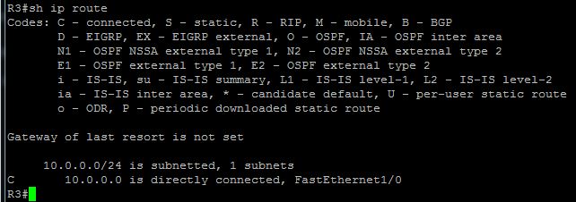 |
| Notice that R3 does not have a default from R1 because R1 does not have a connection to R4 and R3 does not have a default from R2 because R2's fast1/0 which connects to the OSPF is down. |
As of right now this is the topology with certain interfaces shut down.

What do we see? I can see that I should still be able to get to the internet by going through R1 --> R2 --> R5 to the internet. Follow the blue arrow.

So why isn't this happening? Why aren't we getting a default route from R1 into R3? How can we make this work?
Well what we would expect to happen is not happening because R1's learned it's default via iBGP. See below.
 |
| R1 has a default from R2 over its iBGP connection but it is not injecting this route into OSPF why? |
To prevent routing loops iBGP learned routes will not be injected into IGP and only eBGP learned routes will be injected into IGP such as OSPF. This is why when R1 had a connection to R4 (eBGP), R3 had a default route because R1 was injecting its eBGP learned default into OSPF.
Is there a way to inject iBGP learned routes into OSPF and use the route highlighted above with the blue arrow? YES!! There is a way, however we should be very cautious -- using route-maps we should only inject EXACTLY what we need into OSPF from iBGP or else we will be creating routing loops.
Below is how you inject iBGP into OSPF using route-maps.
First create a route-map on R1 and R2 and match only the default route.
R1#conf t
R1(config)#route-map DEFONY permit 10
R1(config-route-map)# match ip address prefix-list DEFONLY ** we have already created DEFONLY prefix-list in Part 1 **
R1(config-route-map)#exit
R1(config)#exit
R2#conf t
R2(config)#route-map DEFONY permit 10
R2(config-route-map)# match ip address prefix-list DEFONLY ** we have already created DEFONLY prefix-list in Part 1 **
R2(config-route-map)#exit
R2(config)#exit
Now type this under BGP on R1 and R2.

We are instructing BGP to redistribute iBGP learned routes by "bgp redistribute-internal" and then in OSPF we are redistributing only the default route from iBGP to prevent routing loops. There is a reason why OSPF AD is 110 and iBGP is 200 :)
Now let's take a look at R3 and see how our route redistribution of iBGP into OSPF affects R3.
 |
| As you can see only the default route from R1 made it into R3 and R3 can now ping R4 and R5 and utilize the iBGP connection between R1 and R2. So yes we can now utilize the blue arrow path from above. |
This concludes our blogtorial on "Dual Homed BGP design". There are quite a few ways to do this design and this was one of them. We have discussed some fairly advanced topics and I suggest you check out a few articles on Cisco to better understand the entire setup.
Many more articles to come so stay tuned and as always if you like my posts please subscribe by clicking "Join this site" on the right.
Hi Brother, hope you are doing well.
ReplyDeleteI tried to make your topology on GNS3, its not working for some reason, If you like I can send you the .net gns3 file, you can please advice what could be the reason why its not working.
sure send it to arwinr at gmail.com
Delete