CCIE is not earned by completing the written and passing the lab, CCIE is earned in the 1000s of hours of lab, the 3am wake ups, and the countless of hours of studying ... that's what makes you a CCIE. While you are on this journey you are going to go through a transformation, and you will start to see things differently, you will start to troubleshoot differently, you will start to perceive situations differently and simply put ... you just become one of the best at your craft .... with that being said ....
In part 2 of this series, we will configure 10 CSR routers, and connect it to the virtual switch that we created in Part 1. Unlike many other tutorials on the Internet that demonstrates how to get serial over network to console into the routers, I am going to take a different approach on how to console into the routers. Main reason is that serial over network is only available for either 60 days as a demo or you have to get the enterprise license which is over $2000.
I normally would do it for free but I have had tons of requests and questions regarding the lab setup and scripts. So for a nominal fee I will configure your entire VMWare ESXi server / all the routers / the Linux VMs / auto loading scripts. More importantly it includes an easy to use WEB GUI to load the config files. Contact me via arwinr@gmail.com if you are interested.
Screenshot of the WEB GUI.
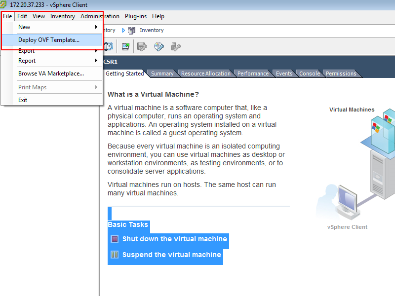
Creating the CSR on VMware
First thing we need to do is get the OVA file from Cisco's website. Note that this does require you to get a free account with Cisco. The one I downloaded at the time of this writing is Cisco CSR 1000V Series ADVANCED ENTERPRISE SERVICES 3.12.0S - OVA (csr1000v-universalk9.03.12.00.S.154-2.S-std.ova). Follow the screenshots
 |
| Browse to the OVA file you downloaded |
 |
| Give it a name |
 |
| Small is fine for now as you will be editing the memory later on. CSR 1000v needs 2.5 GB of RAM or else it wont boot. |
 |
| You could use either Thick or Thin, but better performance by using Thick. |
 |
| By default you will have 3 interfaces, choose the first NIC to be on the network we created in Part 1. We will also use Gig2 for "out-of-band" management to TFTP files and such. Gig3 can be deleted at a later time. |
 |
| Make sure you allocated at least 2.5 GB (perhaps 3GB if you can afford it) of ram. You can also delete the extra NIC (Gig3) if you want. |
 |
| To avoid any issues with booting of the router reserve the entire 2.5 GB for the CSR 1000v. |
 |
| This is where my blog differs from the other tutorials on the internet. Instead of adding a regular Serial Over Network, we are going to add a PIPE. |
After adding the pipe it should looks like this. Later in Part 3 I'll show you how to connect to this pipe to get console into the routers.
Next "power on" the router you just created.
 |
| Pick Virtual console for now. |
 |
| First boot it will install itself on the hard disk and reload automatically. |
 |
| Once it reloads, type no here and continue. |
 |
| Enable the premium license to get advanced features like mpls etc. |
Redirect the console to the serial which is the PIPE we created earlier. Once you do this you wont have Virtual Machine console anymore. However, in Part 3 of this series, I will show you how to get remote console.
I could show you how to clone the first CSR1 and make 10 CSR routers, but in my experience cloning leads to issues, so you are better off just creating 10 routers by following the method above but changing the pipe name to CSR2.pipe CSR3.pipe and so on.
Connecting Physical Switches
Connect the physical switches as below. Make sure to connect SW1 (Gi1/1) to Eth2/vmnic1 of the Hypervisor. Eth2/vmnic1 is assigned to the vSwitch (vSwitch1) we created in Part 1 of this series.
Stay tuned for Part 3 which is coming up next week.
Many more articles to come so ....
Please subscribe/comment/+1 if you like my posts as it keeps me motivated to write more and spread the knowledge.


Amazing Post :) Thank you so much for sharing! I'm eager to read more stuffs here. Please keep posting
ReplyDeleteThanks. Next week Part 3 will contain how to get the physical switches connected and how to upload all the ine initial configs with a slight twist.
DeleteHi, I usually go for GNS3, since it's adaptable and allows integration with QUEMU, Virtualbox, and now even supports IOU.
ReplyDeleteHowever this is an interesting approach....and I have one question.
On IOU, there are still some features that do not work as expected, like QinQ....in this setup do all the "switch" features work?
I tried the GNS route and often the performance wasn't there for 20+ routers and it was buggy at times. Also with my approach there is no breakout switch and no need for Q-in-Q tunneling. If you check out the INE labs you will know what I mean. I suppose you can still use a breakout switch if you want. Also the 4 x switches in this topology are physical switches, only the routers are virtual so the features such PVLANs etc work as expected.
ReplyDeleteThen if I'm understanding correctly, your lab consists on CSR routers running on ESXi, and you'll do the switching part by connecting them to maybe 4 real switches...is that it?
ReplyDeleteYes virtual lab is for all routers and it will connect to 4 real switches.
DeleteSure about 4GB RAM? Should work with default 2.5GB as far as INE and others are stating.
ReplyDeleteI set it to 2600MB and it powered on so I've edited the post accordingly. Thanks!
DeleteHello Guys,
ReplyDeleteDo you know if we have Part 3 of this post yet?
http://ithitman.blogspot.com/2014/12/ccie-v5-ine-part-3-console-to.html .. there it is ..
Delete